US 153 ES
JP09247| Mechanical data | |
|---|---|
| Pump | Vertical single-stage |
| Free passage | 30 mm |
| Bearing | Ball bearings, grease-lubricated |
| Seal on motor side | Duplex rotary shaft seals |
| Oil chamber | Yes |
| Seal on medium side | SiC mechanical seal |
| Run dry protection | Yes |
| Shaft | Stainless steel |
| Impeller | Vortex impeller, GFK |
| Motor housing | stainless steel (253: cast iron) |
| Pump housing | Grey cast iron |
| Submersible | Yes |
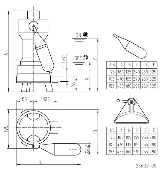
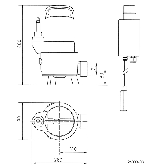
| Pressure outlet | IG 1 1/2" (US253: 2") |
| Weight | 16 kg |
| Electrical data | |
|---|---|
| Ciruit | With built-in level control |
| Voltage | 1/N/PE~230 V |
| Motor rating P1 | 1.6 kW |
| Motor rating P2 | 1.21 kW |
| Current | 7.5 A |
| Power line | 10m H07RN-F |
| Wires | 3G1,0 |
| Type of enclosure | IP 68 |
| Insulation class | B (253:F) |
| Winding thermostat | Yes |
| Motor protection | Integrated |
| Plug | Safety |
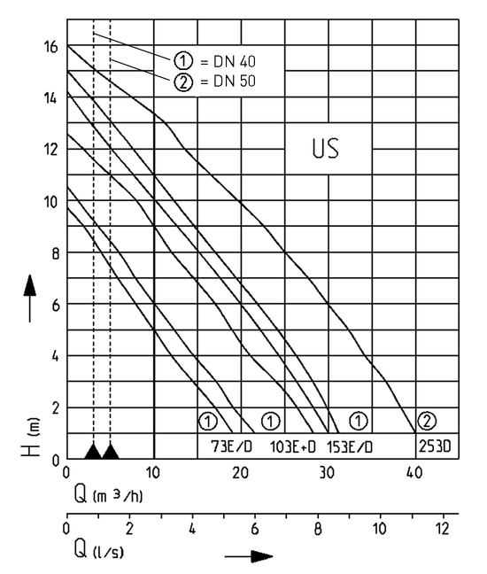
| Performance | ||||||||||||||
|---|---|---|---|---|---|---|---|---|---|---|---|---|---|---|
| Delivery head H [m] | 1 | 2 | 3 | 4 | 5 | 6 | 7 | 8 | 9 | 10 | 11 | 12 | 13 | 14 |
| Flow rate Q [m³/h] | 30 | 29 | 27 | 24 | 22 | 20 | 18 | 15 | 13 | 11 | 8 | 6 | 3 | 1 |
Specifications can be changed without notice. Performance subject to ISO 9906 tolerances.
The minimum flow velocity in the pressure piping must be 0.7 m/s according to EN 12056.
This data is represented in the performance curve as a limit of application.
VDE-Certification for US 73 E/ES, US 103 E/ES
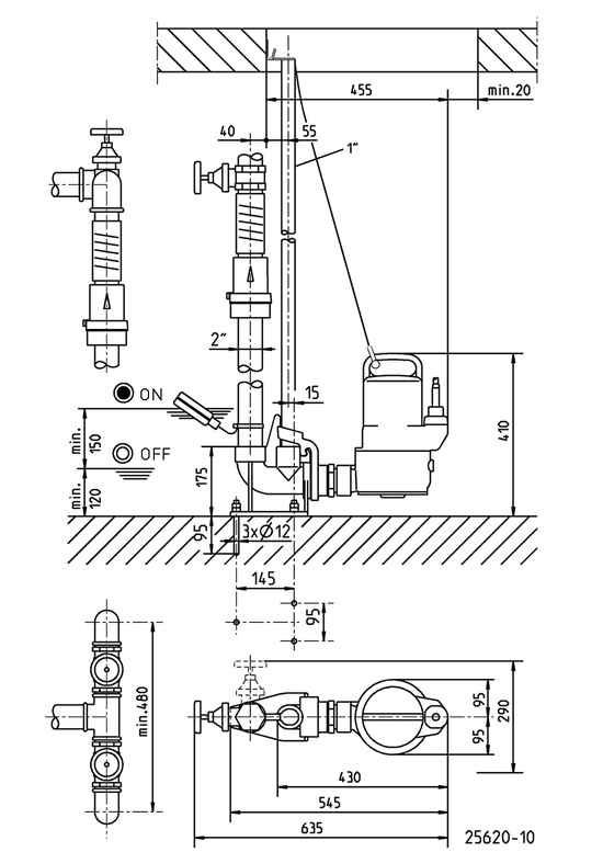
Single unit 1½" with GR 40: sump area min. 40x60 cm
Single unit 1½" without GR: sump area min. 40x40 cm
Single unit 2" with GR 50 S: sump area min. 40x65 cm
Single unit 2" without GR: sump area min. 40x50 cm
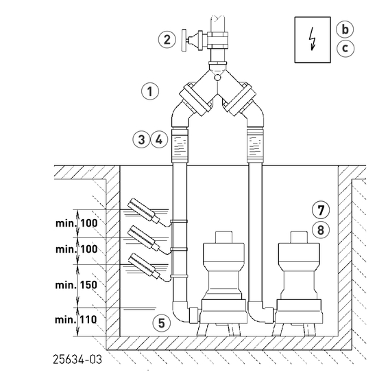
Duplex unit 1½" with GR 40: sump area min. 60x60 cm
Duplex unit 1½" without GR: sump area min. 40x60 cm
Duplex unit 2" with GR 50: sump area min. 70x70 cm
Duplex unit 2" without GR: sump area min. 50x70 cm
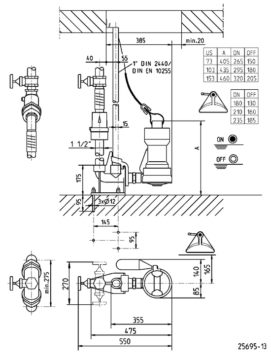
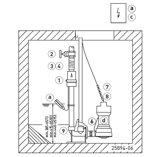
In case of installation beneath the backpressure level the pressure tube must be taken in a loop over the local backup level acc. to EN 12056. Besides, it must be secured with an EN 12050-4-proofed swing-type check valve. Additionally we recommend an alarm system.
In accordance with EN 12056-4 section 5.1, it has a built-in automatic spare pump or a double attachment included, which ensures that sewage drainage is not interrupted.
Suspend control unit in a dry room
| Mechanical accessory | ||||||
|---|---|---|---|---|---|---|
| Code No. | ||||||
| Swing-type check valve | ||||||
| R40 EN 12050-4 | 1½“ (DN 40), PN 4 | 150x120 (HxB) | JP00317 | |||
| Ball-type check valve | ||||||
| KE40 EN 12050-4 | 1½“ (DN 40), PN 6 | 170x125 (HxB) | JP47974 | |||
| Stop valve | ||||||
| brass, 1½“ (DN 40), PN 16 | 125x60 (HxB) | JP44786 | ||||
| Elastic connection | ||||||
| + Hose band clamps, 1½“ (DN 40), PN 4 | 120x50 (HxD) | JP50902 | ||||
| Elbow | ||||||
| 1½“ | JP45953 | |||||
| Special float | ||||||
| for lower switching points | JP44795 | |||||
| Chain | ||||||
| certified, 2.5 m, 320 kg, 5 rings (EN 818 mod.) | JP45901 | |||||
| certified, 5.0 m, 320 kg, 8 rings (EN 818 mod.) | JP45902 | |||||
| certified, 7.5 m, 320 kg, 11 rings (EN 818 mod.) | JP47365 | |||||
| Webbing | ||||||
| with shackle | JP45168 | |||||
| Guide rail system | ||||||
| GR 40 | JP25592 | |||||
| Electrical accessory | ||||||
|---|---|---|---|---|---|---|
| Code No. | ||||||
| Alarm unit | ||||||
| AG3 | subm. ball contact switch, mains dependent, potential-free contact,3 m cable | JP44891 | ||||
| AG10 | subm. ball contact switch, mains dependent, potential-free contact, 9.5 m cable | JP44892 | ||||
| Washing machine stop | ||||||
| AW3 | subm. ball contact switch, mains dependent, 3 m cable | JP44895 | ||||
| AWO | for alarm forwarding in case of several washing machines | JP44899 | ||||
| Level control | ||||||
| Subm. switch pack B | 3 subm. ball contact switch with 9.5 m and fixing devices | JP16725 | ||||
| Rechargeable battery | ||||||
| 9 V, for mains independent alarm | JP44850 | |||||
| Seal leak detector | ||||||
| DKG (für die Ölkammer) | JP44900 | |||||