MultiFree 45/4 CW2, Ex
JP47237| Mechanikai adatok | |
|---|---|
| Szivattyú | függőlegesen egyfokozatú |
| Rb-védelem | rb-védelemmel |
| Szabad átmenet | 100 mm |
| Csapágy | Zsírkenésű golyóscsapágyak |
| Motoroldali tömítés | 2-szeres tengelytömítő gyűrű, 55-től/: Csúszógyűrű tömítés |
| Olajkamra | igen |
| Közegoldali tömítés | SiC csúszógyűrűs tömítés |
| Szárazmenetbiztos | igen |
| Járókerék | Vortex-járókerék, lágyvas |
| Motorház | szürkeöntvény |
| Szivattyúház | szürkeöntvény |
| Elárasztható | igen |
| Nyomócsonk | DN 100 |
| Súly | 81 kg |
| Villamos adatok | |
|---|---|
| Feszültség | 3/PE~400 V |
| Motorteljesítmény P1 | 5,3 kW |
| Motorteljesítmény P2 | 4,2 kW |
| Áram | 9,3 A |
| Hálózati vezeték | 10m H07RN-F |
| Kábelerek | 6G1,5 |
| Védettség | IP 68 |
| Tekercstermosztát | igen |
| Készülékbiztosítás | 10 A |
| S3 | 10 % |
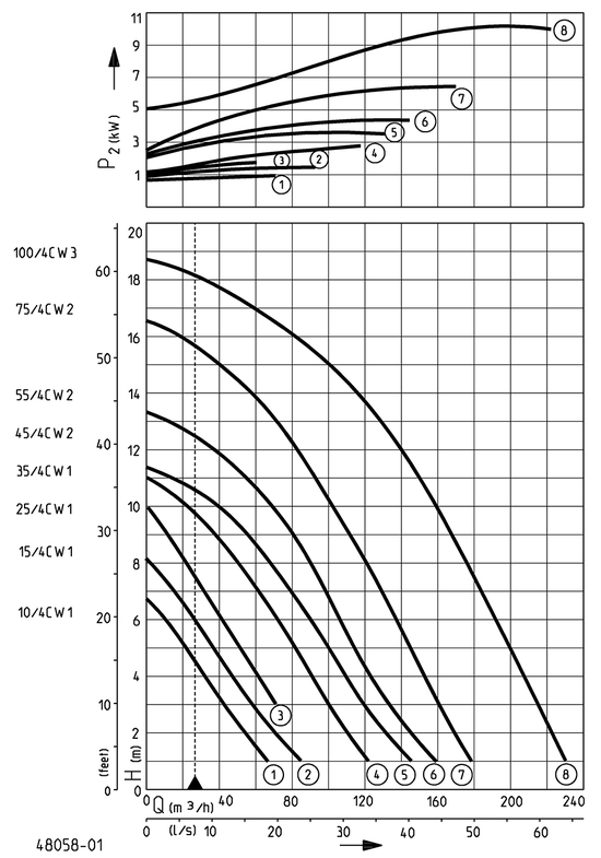
| Teljesítmény | ||||||||||
|---|---|---|---|---|---|---|---|---|---|---|
| Szállítási magasság H [m] | 1 | 2 | 3 | 4 | 5 | 6 | 7 | 8 | 9 | 10 |
| Szállítási mennyiség Q [m³/h] | 142 | 130 | 118 | 108 | 98 | 85 | 79 | 68 | 56 | 43 |
| Szállítási mennyiség Q [l/min] | 0 | 0 | 0 | 0 | 0 | 0 | 0 | 0 | 0 | 0 |
Konstrukciós változtatások joga fenntartva – Teljesítménytolerancia ISO 9906 szerint
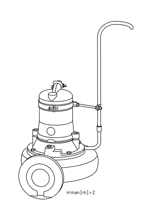
A v = 0,7 m/s minimális áramlási sebesség a nyomóvezetékben (nyomászárás) alkalmazási határértékként látható a Q-H diagramon.
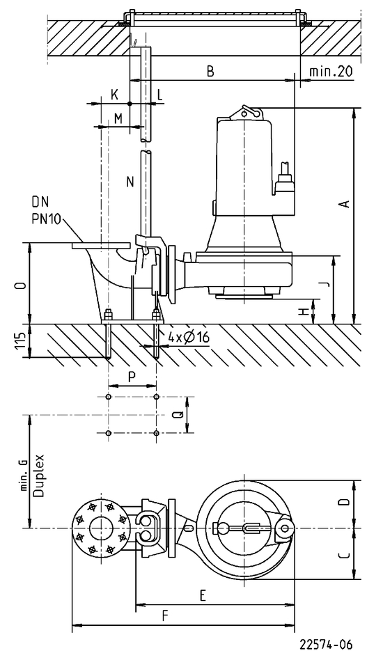
Csúszócső rendszer beépítési méretei
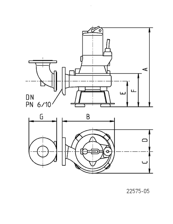
A támaszláb beépítési méretei
Szivattyú nyomáskimenet
Az öblítőcső minimális szállítómagassága (m)
| A csúszócső beépítési méretei | |
|---|---|
| GR | 101 |
| DN | 100 |
| A | 710 mm |
| B | 635 mm |
| C | 195 mm |
| D | 195 mm |
| E | 620 mm |
| F | 860 mm |
| G | 480 mm |
| H | 135 mm |
| J | 330 mm |
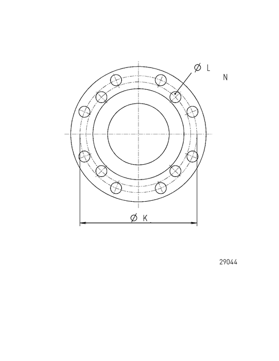
| K | 110 mm |
| L | 55 mm |
| M | 82 mm |
| N | 1" |
| O | 345 mm |
| P | 175 mm |
| Q | 385 mm |
| A tartóláb beépítési méretei | |
|---|---|
| DN | 100 |
| A | 720 mm |
| B | 490 mm |
| C | 195 mm |
| D | 195 mm |
| E | 245 mm |
| F | 335 mm |
| G | 230 mm |
| K | 180 mm |
| L | 18 mm |
| N | 8 |
| Z [m] | 6 mm |
Beépítési példa csúszócsöves rendszerre
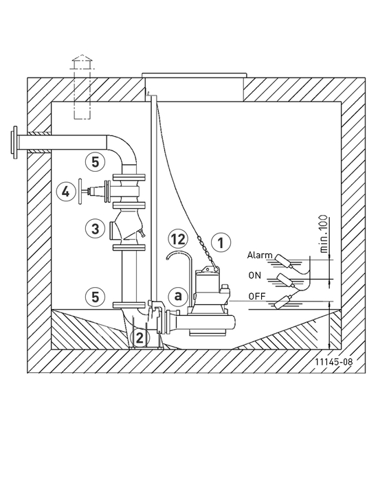
A szükséges tartozékokat és kiegészítő felszereléseket lásd a kezelőszerveknél
| Mechanical accessory | ||||||
|---|---|---|---|---|---|---|
| Cikkszám | ||||||
| Lánc | ||||||
| tesztelt, 2,5 m, 320 kg, 5 függesztőkar (EN 818 mod.) | JP45901 | |||||
| tesztelt, 5,0 m, 320 kg, 8 függesztőkar (EN 818 mod.) | JP45902 | |||||
| tesztelt, 7,5 m, 320 kg, 11 függesztőkar (EN 818 mod.) | JP47365 | |||||
| Bilincs, tesztelt, 630 kg, rozsdamentes acél | JP45904 | |||||
| Szivattyú felfüggesztés (08 Ex - 100...) | JP45925 | |||||
| Vezetőcső rendszer | ||||||
| GR 101 | DN 100, 235x254x345 (ho x szé x ma) | JP21037 | ||||
| Visszacsapószelep | ||||||
| R 101 EN 12050-4 | DN 100, PN 4, perem PN 10, EN 558, 300 (H) | JP00325 | ||||
| R 100 G EN 12050-4 | DN 100, PN 4, perem PN 10, EN 558, ellensúllyal, 300(H) | JP00324 | ||||
| Lapos tolattyú ékkel | ||||||
| DN 100, PN 10, EN 1171 | 345x190 (ma x szé) | JP00329 | ||||
| Elasztikus kötés | ||||||
| + Bilincs, 2“ DN 100, PN4 | 200x110 (ma x mé) | JP50905 | ||||
| + Bilincs, 2“ DN 100, PN4 | 200x114 (ma x mé) | JP50906 | ||||
| Nadrágelem | ||||||
| DN 100/100/100 | 355x480(ma x szé), PN 10 | JP00203 | ||||
| Támaszláb | ||||||
| C 325, a C2,CW2 számára | 145x565 (ma x szé) | JP00701 | ||||
| Karimacsatlakoztatás | ||||||
| C 100 (hasonló Q-elem 90°), DN 100 PN10/PN6 | 175x120 (ma x szé) | JP00579 | ||||
| Öblítőcső | ||||||
| Típus I | 10/... - 45/... | JP28221 | ||||