MultiStream 25/2 A2, Ex
JP50389| Mechanical data | |
|---|---|
| Pump | Vertical single-stage |
| Ex-proof | With ex-proof |
| Free passage | 40 mm |
| Bearing | Ball bearings, grease-lubricated |
| Seal on motor side | Duplex shaft seal, from 55/: mechanical seal |
| Oil chamber | Yes |
| Seal on medium side | SiC mechanical seal |
| Run dry protection | Yes |
| Impeller | Channel impeller, grey cast iron from 55/2... spheroidal grapfite iron |
| Motor housing | Grey cast iron |
| Pump housing | Grey cast iron |
| Submersible | Yes |
| Pressure outlet | DN 65 |
| Weight | 48 kg |
| Electrical data | |
|---|---|
| Voltage | 3/PE~400 V |
| Motor rating P1 | 2.6 kW |
| Motor rating P2 | 2.1 kW |
| Current | 4.4 A |
| Power line | 10m H07RN-F |
| Wires | 6G1,5 |
| Type of enclosure | IP 68 |
| Fuse | 10 A |
| S3 | 40 % |
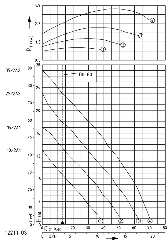
| Performance | |||||||||||||||
|---|---|---|---|---|---|---|---|---|---|---|---|---|---|---|---|
| Delivery head H [m] | 1 | 2 | 3 | 4 | 5 | 6 | 7 | 8 | 9 | 10 | 12 | 14 | 16 | 18 | 20 |
| Flow rate Q [m³/h] | 62 | 60 | 58 | 56 | 54 | 51 | 48 | 46 | 42 | 39 | 33 | 27 | 20 | 13 | 7 |
Specifications can be changed without notice. Performance subject to ISO 9906 tolerances.
The minimum flow rate in the pressure pipe of v = 0,7 m/s is marked in the Q-H-diagram (operative limit).
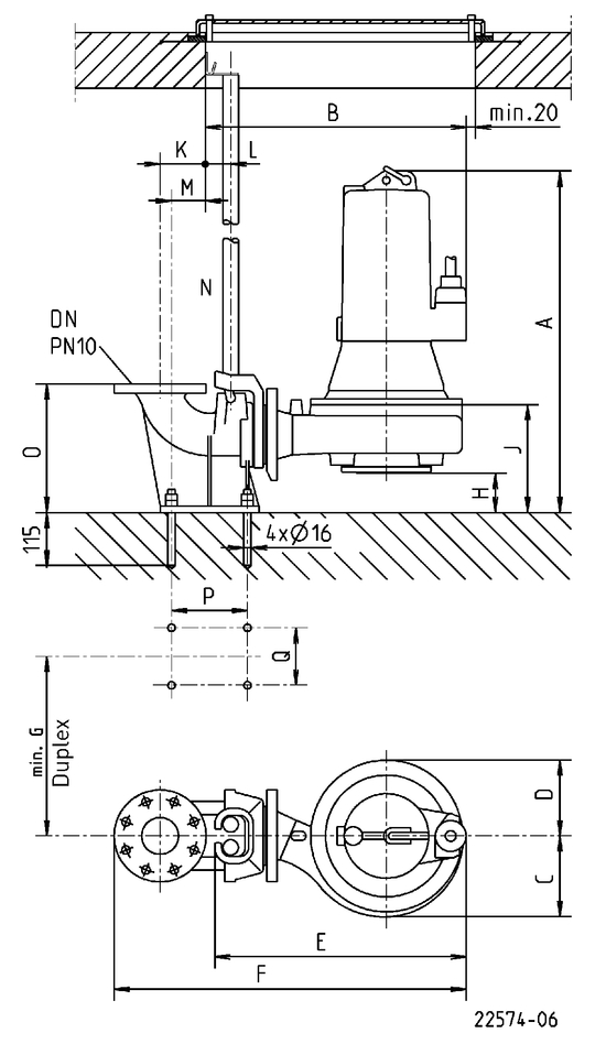
Dimensions guide rail system
Dimensions pump base
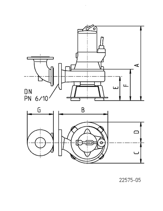
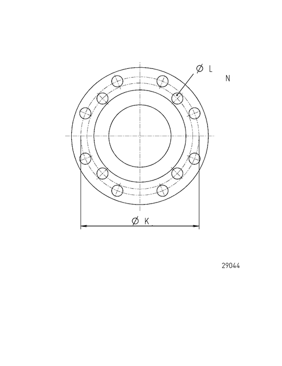
Discharge outlet
| Mounting arrangement with guide rail system | |
|---|---|
| GR | 65 |
| DN | 80 |
| A | 510 mm |
| B | 480 mm |
| C | 130 mm |
| D | 125 mm |
| E | 455 mm |
| F | 680 mm |
| G | 390 mm |
| H | 108 mm |
| J | 220 mm |
| K | 100 mm |
| L | 55 mm |
| M | 74 mm |
| N | 1" |
| O | 280 mm |
| P | 165 mm |
| Q | 125 mm |
| Mounting arrangement with base | |
|---|---|
| DN | 65 |
| A | 475 mm |
| B | 345 mm |
| C | 135 mm |
| D | 135 mm |
| E | 135 mm |
| F | 185 mm |
| G | 175 mm |
| K | 145 mm |
| L | 18 mm |
| N | 4 |
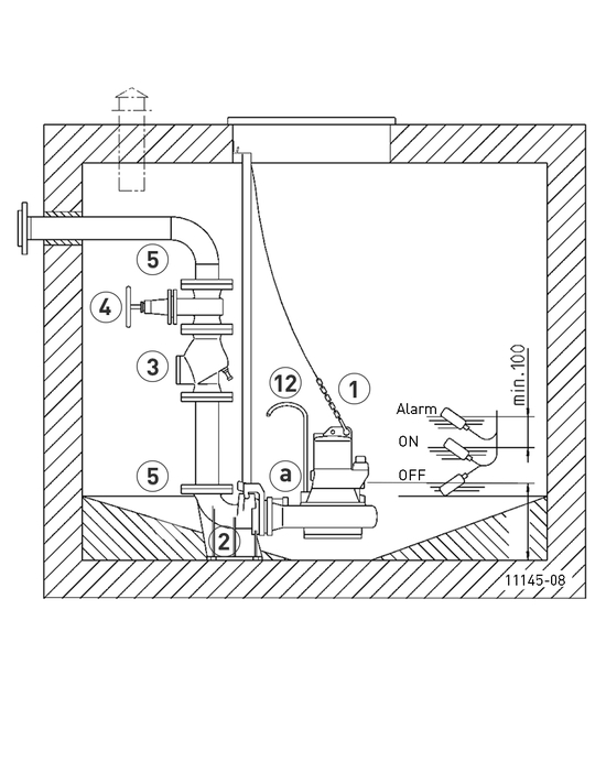
Example of installation guide rail system
Additional requirements, see technical data control units
| Mechanical accessory | ||||||
|---|---|---|---|---|---|---|
| Code No. | ||||||
| Chain | ||||||
| certified, 2.5 m, 320 kg, 5 rings (EN 818 mod.) | JP45901 | |||||
| certified, 5.0 m, 320 kg, 8 rings (EN 818 mod.) | JP45902 | |||||
| certified, 7.5 m, 320 kg, 11 rings (EN 818 mod.) | JP47365 | |||||
| Shackle, certified, 630 kg, stainless steel | JP45904 | |||||
| Pump hanging (08 Ex - 100...) | JP45925 | |||||
| Guide rail system | ||||||
| GR 65 | DN 80, 170x226x280 (AxBxH) | JP00494 | ||||
| Swing-type check valve | ||||||
| R 80 EN 12050-4 | DN 80, PN 4, flange PN 10, EN 558, 260 (H) | JP00706 | ||||
| R 80 G EN 12050-4 | DN 80, PN 4, flange PN 10, EN 558, with counter weight, 260 (H) | JP00707 | ||||
| Ball-type check valve | ||||||
| K 80 EN 12050-4 | DN 80, PN 4, flange PN 10, EN 558, 260 (H) | JP49205 | ||||
| Sluice valve | ||||||
| DN 80, PN 10, EN 1171 | 315x180 (HxB) | JP00639 | ||||
| Flanged spigot | ||||||
| DN 80 PN 10, F-KS | 75x90 (HxD) | JP00686 | ||||
| DN 80 PN 10, F-KS | 85x110 (HxD) | JP00687 | ||||
| DN 80/100, PN 10, F-piece | 76x114 (HxD) | JP09821 | ||||
| Elastic connection | ||||||
| + Clamps, 2“ DN 80 | 200x90 (HxD) | JP50904 | ||||
| Flanged Y-pipe | ||||||
| DN 80/100/80 | 355x390(HxB), PN 10 | JP00448 | ||||
| DN 80/100/80 | 355x480(HxB), PN 10 | JP00202 | ||||
| Reducing adapter | ||||||
| DN 80/100 to PN 10, (similar FFR-piece), H=100 | JP00498 | |||||
| Pump base | ||||||
| A 220, for A2, AW1, AW2 | 90x295 (HxB) | JP00682 | ||||
| Flanged connection | ||||||
| A 80 (similar Q-piece 90°), DN 80 PN10/DN 65 PN6 | 130x75 (HxB) | JP00577 | ||||
| Flushing tube | ||||||
| Type I | 10/... - 45/... | JP28221 | ||||